|
|||||||||||||||||||||||||||||||||||||||||||||||||||||||||
|
|
|||||||||||||||||||||||||||||||||||||||||||||||||||||||||
|
Terminal Block Manufacturing Residue IssuesArticle source link
Do manufacturing residues, specifically ionic residues, have an affect on terminal blocks that can impact electronic product quality? As a failure analysis lab we have seen problems where corrosion on the terminal blocks was affecting product performance. The following is summary of an analysis for a client who had galvanic corrosion on terminal block assemblies that had to be replaced. The
goal was to determine the root cause and develop a corrective action plan. Terminal block assemblies were built using an organic acid flux (OA), which is typically chloride activated, and cleaned in an inline aqueous cleaner using city processed tap water. The boards were air dried for 24 hours at room temperature then placed in ESD bags and packaged, standing on edge, in boxes.
Both ion chromatography (IC), per IPC-TM-650 2.3.28, and surface insulation resistance (SIR), per IPC-TM-650 3.2.3.3a, testing were used to evaluate this problem. The information from IC testing shows, among other things, the chloride (CL-), bromide (Br-), and weak organic acids (WOAs) levels that are potential threats to product quality. The SIR results show the effects of surface residues on electrical performance between leads under power in high temperature and humidity conditions (85oC / 85 % RH). The data from the ion chromatography evaluation is shown in the following table. The IC data is shown as micrograms of the residue species per square inch of extracted surface. This measure should not be confused with micrograms of sodium chloride equivalent per square inch, which is the common measure for most ionic cleanliness test instruments. Ion Chromatography Test Results
1 Bromide is generally attributable to the bromide fire retardant added to epoxy-glass laminates to give fire resistance. Bromide can also come from solder masks, marking inks or from fluxes that have a bromide activator. When the bromide is from the fire retardant it is not considered to degrade long-term reliability. If the bromide is from a flux residue, then it can be as corrosive as other halides. The amount of bromide residue can vary depending on the porosity of the laminate and/or mask, the degree of over/under cure of the laminate or mask, or the number of exposures to reflow temperatures the assembly experiences. Bromide findings on the tested samples fell within an acceptable level of bromide residue and pose a low risk of electrical leakage or corrosion due to bromide. Weak organic acids (WOAs), such as adipic or succinic acid, are used as activator compounds in many fluxes. WOA levels vary greatly depending on the delivery method and the preheat dynamics and are an indicator of the cleaning efficiency. The findings show high levels of WOAs on these assemblies indicates poor cleaning performance of their tap water cleaning system. The high WOA levels can cause electrical leakage problems. Remedial cleaning of the assemblies showed a great reduction of the WOA residues. This low level poses minimal to no risk of electrical leakage problems. Chloride is one of the more detrimental materials found on printed circuit assemblies. Chlorides can come from a variety of sources, but are most often attributable to flux residues. Chlorides will generally initiate and propagate electrochemical failure mechanisms, such as metal migration, electrolytic, and galvanic corrosion, when combined with water vapor and electrical potential. The amount of chloride that can be tolerated on an assembly depends on the flux chemistry being used. Assemblies processed with high-solids rosin fluxes (RA, RMA) can tolerate higher levels of chloride due to the encapsulating nature of the rosin. Water-soluble fluxes and no-clean fluxes are generally based on resins or very low levels of rosin, and so do not have this encapsulating protection; therefore they require lower levels of residues on final assemblies. Chloride findings show that the boards were processed with water-soluble flux and our recommendations are for chloride levels below 4.5 micrograms per square inch on the final assembly. We consider the assemblies As Received to be above recommended levels and the source of the corrosion on the brass and contact areas. Remedial cleaning of the connector areas showed great reductions on the surface of the assemblies. These chloride levels after cleaning were well below our recommended limits and pose no problems for corrosion or electromigration. 2 Surface insulation resistance (SIR) testing was performed on 12 boards. Six assemblies were taken from the dirty (As Received) group and six assemblies were taken from the post-cleaning group. All six boards from the remedial cleaning process performed well with no visual signs of electromigration. All six boards from the As Received group showed low levels of SIR and failed the IPC requirement of 1.0E 8 ohms of resistance. The As Received boards all showed performance and metal migration problems. This corresponds to the ion chromatography results. Surface Insulation Resistance Test Results
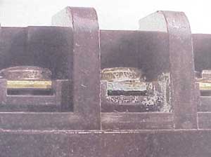
Failure Scenario: The terminal block assemblies were run through the in-line cleaner with the blocks up. This would have held wash water inside the cells of the terminal blocks. The cells did not have any drain holes. Heavy flux laden wash water was naturally spayed onto the boards during the time in the wash section and not all cells were flushed properly. The rinsing and drying removed most of the water and flux from most of the cells, but not all of them. The wash protocol was not effective at removing the overall flux residues to a level necessary for long-term reliability. Based on test data and previous experience we can answer the following questions:
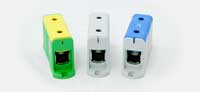
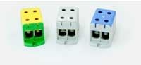
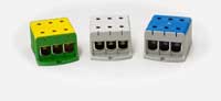
Conclusions There are currently two problems that these assemblies face. First, the galvanic corrosion of the brass contact point on the terminal block will not allow flow of electricity. Second, the flux residues remaining on the assemblies create substantial risk of electrical leakage and/or electromigration problems in the field. Moral of the Story Do not wash terminal blocks on assemblies. Attach after assembly and cleaning of the circuit boards or assemble with no-clean flux. Al/Cu Terminal Blocks you can find here:
|
||||||||||||||||||||||||||||||||||||||||||||||||||||||||
Elit OÜ | e-post:
elit@elit.ee | GSM: +372 6229119 | 2013 ©
|
|||||||||||||||||||||||||||||||||||||||||||||||||||||||||